
2022.08.02
Vacuum Control in Low Pressure Buffer Tank - Proportional Flow Control Valves Duet Application
SHARE
MORE DETAIL
Vacuum Control in Low Pressure Buffer Tank
Abstract: Low-pressure buffer tanks are widely used in various vacuum processes and equipment. This article mainly focuses on the use of proportional flow control valve to precisely control the vacuum degree of buffer tank in the full range, and proposes corresponding solutions according to different vacuum degree ranges and the volume of buffer tank to meet the different requirements for precise control of buffer tank vacuum pressure in different low-pressure processes.
1. Introduction
A low pressure buffer tank is a type of vacuum container commonly used in vacuum systems to prevent excessive circulation of vacuum pumps by providing vacuum "storage". The basic principle of which is to use hold-up (volume) to provide a smoother vacuum operation. During the vacuum process, the low pressure buffer tank mainly has the following two structural forms:
The low pressure buffer tank mainly has the following two structural forms:
(1) Attenuation of vacuum degree fluctuations: The buffer tank is installed between vacuum units to avoid the spread of vacuum degree fluctuations in the continuous process.
(2) Independent operation: Buffer tanks are installed between units to allow independent operation, such as during temporary shutdowns and between continuous and batch units.
In the form of independent operation, the low-pressure buffer tank generally needs to have the following functions:
(1) For process vessels with small space, it is difficult to achieve high-precision constant vacuum or program control, and the fluctuation and inaccuracy of vacuum are difficult to meet the process requirements. For this, a low pressure buffer tank with a large volume is connected in series on the process vessel, and this problem can be perfectly solved by precise control of the vacuum degree of buffer tank.
(2) Provide gas-liquid separation function to prevent the working liquid from being directly poured into the vacuum pump.
(3) Provide condensation function to prevent part of the solvent in the reaction vessel from being converted into gas and directly entering the vacuum pump, thereby reducing the failure rate of vacuum pump and improving the service life of vacuum pump.
This article mainly aims at the use of proportional flow control valve to precisely control vacuum degree of buffer tank in the full range, and proposes corresponding solutions to meet the different requirements for the precise control of vacuum pressure of buffer tank in different low-pressure processes.
2. Solution
In the process of precise control of vacuum degree for low pressure buffer tank, the basic control method is to adjust the air intake and outlet flow of buffer tank, and reach accurate control of internal pressure of buffer tank through the dynamic balance of inlet and outlet flow, which is the so-called dynamic balance method. However, in different vacuum processes and equipment, there will be different requirements for the vacuum range of low-pressure buffer tank, and the corresponding dynamic control modes are also different. Moreover, low-pressure buffer tanks of different sizes require different adjustment devices in order to reach rapid and accurate control of vacuum degree in buffer tank. For these different requirements, corresponding specific solutions and related device details will be proposed below.
2.1 Low vacuum (high pressure) and high vacuum (low pressure) control methods
Generally, we refer to the absolute pressure below one atmosphere (760Torr) as vacuum (or low pressure), and the entire vacuum range is divided into low vacuum (10-760Torr), high vacuum (0.01~10Torr) and ultra-high vacuum ( <0.01Torr) in three parts. This article will only cover the precise control of the vacuum degree in the two ranges of low vacuum and high vacuum. For ultra-high vacuum, there is no good technical means for precise control, and it is basically only achieved by the pumping capacity of vacuum pump in the order of magnitude control.
In the dynamic balance method control of vacuum degree of low vacuum and high vacuum buffer tanks, in order to reach fast and accurate control effects, two control modes, upstream and downstream, must be used respectively. The switch can reach precise control of the full range of vacuum.
The overall structure of low-pressure buffer tank dynamic balance method vacuum degree control system is shown in Figure 1. The entire buffer tank vacuum degree control system is mainly composed of intake valve, exhaust valve, vacuum pump, vacuum sensor and PID controller. Their respective functions are as follows:
(1) The role of the intake proportional flow control valve is to adjust the intake flow. During the vacuum control process of buffer tank, the intake air flow is generally adjusted within a small range, so the intake valve is generally an electric needle valve.
(2) The function of the exhaust proportional flow control valve is to adjust the air flow. In the process of vacuum degree control of the buffer tank, the intake air flow is generally adjusted within a large range, so the diameter of the intake valve generally needs to be configured according to the needs, which will be described in detail later.
(3) The role of the vacuum pump is to provide a vacuum source. During the vacuum degree control process of the buffer tank, the vacuum pump should be selected according to the vacuum degree requirements and the volume of the buffer tank.
(4) The function of vacuum sensor is to measure the vacuum degree of buffer tank in real time and feed back the measurement signal to PID control. During the vacuum degree control process of buffer tank, sensors should be selected according to the vacuum degree range and accuracy requirements of buffer tank. A vacuum gauge should be generally equipped in each of the low vacuum and high vacuum ranges. In order to ensure the measurement accuracy, a capacitive vacuum gauge is generally selected.
(5) The function of PID controller is to adjust intake proportional flow control valve and exhaust proportional flow control valve respectively through the received vacuum degree signal, so that the vacuum degree in buffer tank reaches the set value or changes according to the set program. In the vacuum degree control in the full range, if two vacuum gauges with different ranges are required to cover the full range, a dual-channel PID controller with automatic sensor switching function is required, so that the control process in different ranges can be carried out to switch automatically. If a capacitive vacuum gauge is used to reach high-precision vacuum control, the corresponding PID controller needs to have 24-bit A/D and 16-bit D/A high precision.
In the different vacuum range of buffer tank, the following different control modes are required to satisfy the control accuracy.
(1) Upstream control mode: The upstream control mode is also called the intake adjustment mode, which is mainly suitable for precise control in the high vacuum range. In the upstream control mode, the exhaust proportional flow control valve is basically fully open and exhausted at full speed, and the precise control of high vacuum in buffer tank is reached by adjusting air intake flow.
(2) Downstream control mode: The downstream control mode is also known as the air outlet adjustment mode, which is mainly suitable for precise control in the low vacuum range. In the downstream control mode, the intake proportional flow control valve is basically a fixed opening, that is, the intake flow is fixed, and the precise control of low vacuum in buffer tank is reached by adjusting the exhaust flow.
In addition, it should be noted that no matter which control mode is adopted, the control accuracy is also limited by the vacuum sensor and PID control accuracy. Therefore, in addition to selecting reasonable upstream and downstream control modes, it is also necessary to select reasonable sensors and controllers according to different accuracy requirements.
2.2 Vacuum control of different buffer tank volumes
In the precision control of the vacuum degree of the buffer tank, in addition to the above-mentioned control mode selection, it also involves the control speed problem, that is, according to the volume size of the buffer tank and the vacuum degree control range, a reasonable vacuum degree and accurate control speed are determined. This aspect mainly involves the following two aspects and basic principles:
(1) For the buffer tank with small volume, the intake proportional flow control valve, exhaust proportional flow control valve and vacuum pump with small flow adjustment capability can be selected.
(2) For a buffer tank with a larger volume, an intake valve, an exhaust valve and a vacuum pump with a larger flow adjustment capability may be required.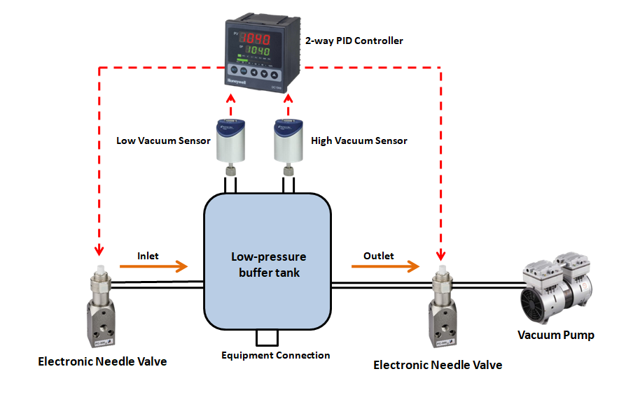
For further information about the proportional flow control valve, please visit:
https://www.genndih.com/proportional-flow-control-valve.htm